Part Warranty, Return and Ordering information
How to order parts or request an RMA from Xerox:
(U.S. and Canada only)Call 800-835-6100
(and follow these steps):
- Option 9 (Placing an Order)
- Option 3 (Parts and Upgrades)
- Option 1 (Phaser and DocuPrint N series printers)
Note:
Not all parts shown are available individually, but may be available as part of an assembly.
Some parts are not part numbered and therefore not orderable.
Warranty information:
All parts have a 90 day warranty.
Contact Xerox Technical Support:
800-835-6100 for warranty part replacement.
Part returns: RMA is required prior to returning any part
- Unopened parts may be returned within 90 days of purchase.
- There is a 5% restocking fee for all returned parts.
Contact Xerox for a Return Material Authorization (RMA). (See "How to order parts or request an RMA from Xerox" above)
- Opened parts are non-returnable.
|
Using the Parts Lists
The Parts Lists section provides exploded view illustrations of all spared subsystem components and a listing of the corresponding part numbers. The illustrations show the relationships between parts.
- Each callout number in an illustration corresponds to an item number in the parts list for that illustration.
- The capital letters "C", "E", "KL", and "S", that appear in some illustrations stand for C-ring, E-ring, KL clip, and Screw, respectively.
- A shaded triangle in an illustration indicates the item is part of an assembly.
- A notation such as "1 (with 2~4),"; means part 1 consists of parts 2, 3, and 4.
- An asterisk * following a part name indicates the page contains a note about this part.
- The notation "J1<>J2 and P2" is attached to a wire harness. It indicates that connector jack 1 is attached to one end of the wire harness and connector jack 2 is attached to the other end that is plugged into plug 2.
- The following abbreviations are used in the parts lists text and illustrations:
P/J – Plug/Jack
P/O – Part of
W/ – With
W/O – Without
|
|
Contents:
The Phaser 4400 Parts List/Diagrams are also available in PDF format
|
PL 1.1 Covers (1 of 2)

| Item |
Part |
Description |
| 1 |
48E64591 |
Left Cover |
| 2 |
802K11331 |
Left Interface Cover |
| 3 |
48E64642 |
Option Cover |
| 4 |
48K76455 |
Top Cover Assembly |
| 5 |
101K38280 |
Front Panel Assembly |
| 6 |
962K09691 |
Front Panel Harness Assembly |
| 7 |
48E64612 |
Right Cover |
| 8 |
802K36773 |
Front Cover Assembly (with 9-12, 14-16, 18, 19, 26) |
| 9 |
|
Front Cover (P/O item 8) |
| 10 |
|
Left Latch Assembly (P/O item 8) |
| 11 |
|
Lever (P/O item 8) |
| 12 |
|
Right Latch Assembly (P/O item 8) |
| 13 |
3E48991 |
Cover Stopper |
| 14 |
|
Envelope Chute |
| 15 |
3E43880 |
Tray Stopper |
| 16 |
50K47271 |
MPT Tray Assembly |
| 17 |
802K44310 |
Left Front Cover |
| 18 |
|
MPT Chute (P/O item 21) |
| 19 |
|
MPT Cleaning Pad Assy. (P/O item 21) |
| 20 |
Not used |
Not used |
| 21 |
604K04790 |
MPT Cleaning Kit (with 18, 19, and PL 4.1 item 5) |
| 22 |
|
Spring joint |
| 23 |
|
Front cover spring |
| 24 |
|
Env gear cover |
| 25 |
|
Exit 2 grounding spring |
| 26 |
|
Clip |
| KL |
354W24254 |
KL Clip |
| S |
600K79660 |
Hardware Kit (Includes Screw) |
<< Back to Top of Page
PL 1.2 Covers (2 of 2)
| Item |
Part |
Description |
| 1 |
|
Latch Spring |
| 2 |
|
Left Latch |
| 3 |
|
Right Latch |
| 4 |
|
Latch Cover |
| 5 |
|
Rear Cover |
| 6 |
|
Direction Arm |
| 7 |
600K83121 |
Cap Kit (quantity 2) |
| 8 |
54K14992 |
Face Up Chute Assembly |
| 9 |
|
Right Pivot Stopper |
| 10 |
3E46120 |
Stopper |
| 11 |
32E12671 |
Duplex Guide Rail-Left |
| 12 |
32E12681 |
Duplex Guide Rail-Right |
| 13 |
802K10013 |
Rear Cover Assembly (with 1-9) |
| S |
600K79660 |
Hardware Kit (Includes Screw) |
<< Back to Top of Page
PL 2.1 Tray 1 (1 of 2)

| Item |
Part |
Description |
| 1 |
109R00448 |
Cassette Assembly (with 2-20 and PL 2.2) |
| 2 |
|
Bottom Plate Assembly |
| 3 |
|
End Guide Assembly |
| 4 |
|
Extension Housing |
| 5 |
|
Rack Slide |
| 6 |
|
Extension Spring |
| 7 |
|
Latch Spring |
| 8 |
|
Size Plate |
| 9 |
|
Base Extension |
| 10 |
|
Left Side Guide Assembly |
| 11 |
|
Right Side Guide Assembly |
| 12 |
|
Link |
| 13 |
|
Tray 1 Base |
| 14 |
|
Rack |
| 15 |
|
Pinion |
| 16 |
|
Cassette Sub-Assembly (PL 2.2) |
| 17 |
|
Tray 1 Actuator |
| 18 |
|
Actuator Cover |
| S |
600K79660 |
Hardware Kit (Includes Screw) |
<< Back to Top of Page
PL 2.2 Tray 1 (2 of 2)

| Item |
Part |
Description |
| 1 |
|
Cassette Assembly (with 2-27) (P/O PL 2.1 Item 1) |
| 2 |
|
Retard Cap |
| 3 |
|
Retard Chute Base - Left |
| 4 |
|
Retard Chute |
| 5 |
|
Retard Chute Base - Right |
| 6 |
|
Retard Shaft Assembly |
| 7 |
5K82890 |
Friction Clutch Assembly |
| 8 |
600K79550 |
Roller Assembly Kit |
| 9 |
|
Retard Bracket |
| 10 |
809E11830 |
Retard Spring |
| 11 |
|
Tongue Plate |
| 12 |
|
Tongue Shaft Assembly |
| 13 |
|
Lift Up Shaft Holder |
| 14 |
|
Bearing |
| 15 |
|
Lift Up Ground Spring |
| 16 |
|
Cassette Housing |
| 17 |
|
Lever |
| 18 |
|
Cassette Handle Assembly |
| 19 |
|
Motor Spring |
| 20 |
|
Right Holder |
| 21 |
|
Left Holder |
| 22 |
127K24682 |
Motor Assembly |
| 23 |
|
Motor Holder Assembly |
| 24 |
114E11680 |
Connector |
| 25 |
|
Spring |
| 26 |
|
Socket Guide |
| S |
|
Hardware Kit (Includes Screw) |
<< Back to Top of Page
PL 3.1 Paper Feeder

| Item |
Part |
Description |
Item |
Part |
Description |
| 1 |
22K51531 |
Turn Roller Assembly (with 2) |
25 |
|
O/W Clutch Assembly(P/O item 19) |
| 2 |
121K20151 |
Turn Clutch Assembly |
26 |
|
Roller Assembly (P/O item 48) |
| 3 |
|
Extension Spring |
27 |
|
Gear 25T (P/O item 19) |
| 4 |
809E11630 |
Chute Spring |
28 |
|
Gear 31T (P/O item 19) |
| 5 |
|
Feed CST Cover |
29 |
809E11610 |
Nudger Spring |
| 6 |
120E16960 |
No Paper Actuator |
30 |
|
Gear 4 |
| 7 |
830E18132 |
Actuator Support |
31 |
|
Gear 2 |
| 8 |
|
Feeder Frame Assembly |
32 |
|
Gear Cover |
| 9 |
|
Clamp |
33 |
|
Bracket |
| 10 |
|
Left Latch Spring |
34 |
|
Gear 3 |
| 11 |
|
Low Paper Actuator (P/O item 46) |
35 |
|
Gear 1 |
| 12 |
|
Low Paper Actuator Support (P/O item 46) |
36 |
160K52781 |
Feeder PWB |
| 13 |
130E81970 |
Low Paper Sensor |
37 |
121K19010 |
Feed Clutch Assembly |
| 14 |
162K47211 |
No Paper Sensor Harness Assy. |
38 |
|
Bearing |
| 15 |
|
Roller 7 support |
39 |
|
N/MOT Harness Assembly |
| 16 |
|
Turn Chute |
40 |
|
Socket |
| 17 |
|
Roller 7 |
41 |
|
CST Stopper |
| 18 |
|
Feeder Cover |
42 |
|
Clamp |
| 19 |
600K79320 |
Feed Head Assembly (with 20-28) |
43 |
600K79640 |
Socket & Harness Kit (with 39, 40) |
| 20 |
|
Feed Shaft (P/O item 19) |
44 |
600K79652 |
Actuator & Support Kit (with 11, 12) |
| 21 |
|
Bearing (P/O item 19) |
45 |
22K56902 |
Feeder Assembly 1 Kit (with 1-42) |
| 22 |
|
Nudger Support Assembly (P/O item 19) |
46 |
600K79550 |
Feed Roller Kit (item 26- quantity 3) |
| 23 |
130E81970 |
Stack Height Sensor (P/O item 19) |
S |
600K79660 |
Hardware Kit (includes screw) |
| 24 |
|
Gear Clutch (P/O item 19) |
|
|
|
<< Back to Top of Page
PL 4.1 MPT Chute

| Item |
Part |
Description |
| 1 |
54K22391 |
MPT Chute Assembly (with 2-24) |
| 2 |
|
MPT Shaft Assembly |
| 3 |
|
MPT Pick-up CAM |
| 4 |
|
Core |
| 5 |
22K50815 |
MPT Roller Assembly |
| 6 |
|
MPT (Left) Cam Pick-up |
| 7 |
|
Guide Roller |
| 8 |
|
Bearing |
| 9 |
|
Tray Bottom |
| 10 |
120E17121 |
MPT No Paper Actuator |
| 11 |
|
MPT Bottom Spring Tray |
| 12 |
|
Exit Bearing |
| 13 |
19K94573 |
Retard Pad Assembly |
| 14 |
130E81970 |
Paper Set Sensor |
| 15 |
|
MPT Ground Plate |
| 16 |
|
MPT Chute Assembly |
| 17 |
121E85920 |
Pick Up Solenoid |
| 18 |
809E20171 |
MPT Spring |
| 19 |
7E54661 |
Gear Pick Up |
| 20 |
|
Envelope Connector Plate |
| 21 |
113K82141 |
Envelope Connector Assembly |
| 22 |
162K47021 |
MPT No Paper Harness Assembly (J45-J451) |
| 23 |
19K96830 |
Pick Up Pad Assembly |
| 24 |
604K04790 |
MPT Cleaning Kit (with 5, and 18 and 19 from —PL 1.1 Covers (1 of 2)“.) |
| S |
600K79660 |
Hardware Kit (Includes Screw) |
<< Back to Top of Page
PL 5.1 Paper Handler Assembly

| Item |
Part |
Description |
Item |
Part |
Description |
| 1 |
|
Toner Sensor |
21 |
|
Left Bearing |
| 2 |
|
Toner Sensor Harness Assembly (J42-J421) |
22 |
162K47011 |
Registration Harness Assembly (J43-J431, J432) |
| 3 |
|
TNS Cushion |
23 |
|
Clamp |
| 4 |
|
Toner Sensor Holder |
24 |
7E54650 |
Gear 14 |
| 5 |
|
Toner Sensor Spring |
25 |
6E60981 |
Shaft 14 |
| 6 |
600K79381 |
Toner Sensor Kit (with 1-5) |
26 |
|
Upper Chute Bottom |
| 7 |
|
Metal Registration Roller |
27 |
|
Right Bearing |
| 8 |
|
Torsion Spring |
28 |
809E22950 |
Registration Spring - Right (Silver) |
| 9 |
|
Upper Chute Assembly |
29 |
7E54671 |
Registration Gear (Metal roller) |
| 10 |
|
Chute Inlet |
30 |
|
Right Bearing |
| 11 |
|
Lever Handle |
31 |
7E54681 |
Registration Gear (Rubber roller) |
| 12 |
|
Chute Inlet Cap |
32 |
|
Ground Spring - Right |
| 13 |
59K11910 |
Rubber Registration Roller |
33 |
|
Ground Spring - Center |
| 14 |
|
Ground Spring - Bottom |
34 |
|
Ground Screw |
| 15 |
120E13331 |
Registration Actuator |
35 |
|
Left Spring |
| 16 |
809E19722 |
Registration Sensor Spring |
36 |
|
Baffle Resistor |
| 17 |
130E81970 |
Registration Sensor |
37 |
|
Lower Chute Bottom |
| 18 |
809E19030 |
Registration Spring Left (Gold) |
38 |
|
CST Chute |
| 19 |
|
Bearing |
39 |
54K14986 |
Paper Handler Assembly (with 7-38) |
| 20 |
121E85820 |
Registration Clutch |
S |
600K79660 |
Hardware Kit (Includes Screw) |
<< Back to Top of Page
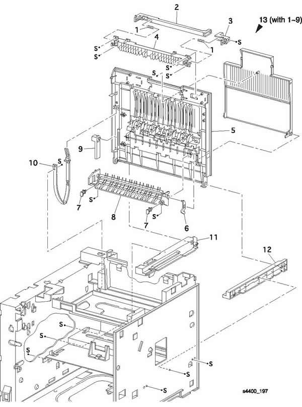
PL 6.1 Chute Transport and Fuser

| Item |
Part |
Description |
| 1 |
22K55010 |
Transfer Roller Assembly |
| 2 |
54K15000 |
Transfer Chute Assembly (with 3-5) |
| 3 |
|
Bearing Transfer Roller SUP |
| 4 |
|
Spring Transfer Roller |
| 5 |
|
Transport Chute |
| 6 |
126K14938 |
Fuser Assembly (120 V) (with 10, 11) |
| |
126K14938 |
Fuser Assembly (230 V) (with 10, 11) |
| 7 |
|
DTS Wire Assembly |
| 8 |
|
TR Wire Assembly |
| 9 |
962K06300 |
Fuser Harness Assembly (120 V) (J271, J11, J27, J262) |
| |
962K06310 |
Fuser Harness Assembly (230 V) (J271, J11, J27, J262) |
| 10 |
802K10003 |
Fuser Upper Cover Assembly |
| 11 |
126K08411 |
Heat Rod (120 V) |
| |
126K09711 |
Heat Rod (230 V) |
| 12 |
|
Thumb Screw |
| 13 |
108R00497 |
Maintenance Kit (120 V) (with Fuser, Transfer Roller, 9 Feed Rollers) |
| |
108R00498 |
Maintenance Kit (230 V) (with Fuser, Transfer Roller, 9 Feed Rollers) |
| S |
600K79660 |
Hardware Kit (Includes Screw) |
<< Back to Top of Page
PL 7.1 Exit

| Item |
Part |
Description |
| 1 |
105K14904 |
Static Eliminator Assembly |
| 2 |
120E13350 |
Stack Full Actuator |
| 3 |
|
Exit Gate |
| 4 |
|
Exit Spring |
| 5 |
|
Exit Gear 17 |
| 6 |
|
Exit Bearing (P/O item 25) |
| 7 |
59K11950 |
MID-1-3 Roller Assembly |
| 8 |
|
Out Exit Pinch Roller |
| 9 |
|
Exit Pinch Roller |
| 10 |
|
Exit Pinch Spring |
| 11 |
59K11960 |
MID-2 Roller Assembly |
| 12 |
|
Pinch Roller |
| 13 |
|
MID Pinch Spring |
| 14 |
|
Pinch Spring |
| 15 |
|
Exit Chute |
| 16 |
130E81970 |
Exit Photo Sensor |
| 17 |
162K46981 |
Stack Full Sensor Harness Assembly (J30-J301) |
| 18 |
|
Interlock Cover |
| 19 |
|
Exit Gear 23 |
| 20 |
|
Exit Gear 33 |
| 21 |
127K35830 |
Exit Motor Assembly |
| 22 |
|
Exit Gear 17/47 |
| 23 |
|
Exit Gear 32 |
| 24 |
|
Exit Ground Spring |
| 25 |
600K79540 |
Bearing Kit (quantity 6 of item 6) |
| 26 |
54K15893 |
Exit Chute Assembly (with 1-17, 19-24) |
| S |
600K79660 |
Hardware Kit (Includes Screw) |
<< Back to Top of Page
PL 8.1 Drive and Xerographics

| Item |
Part |
Description |
| 1 |
113R00627 |
Print Cartridge (10K) |
| |
113R00628 |
Print Cartridge (15K) |
| 2 |
|
Print Cartridge Sensor Harness Assembly (J25-J251) (P/O item 19) |
| 3 |
|
Spring (P/O item 19) |
| 4 |
|
Print Cartridge Sensor Assembly (P/O item 19) |
| 5 |
32K94111 |
Print Cartridge Top Guide Assembly |
| 6 |
162K46922 |
Laser Harness Assembly (J21-J211, J212, J213) |
| 7 |
62K11210 |
Laser Assembly |
| 8 |
|
Print Cartridge Side Guide Assembly-R (with 9, 10, 13-16) |
| 9 |
|
Print Cartridge Side Guide |
| 10 |
|
Spring Clip |
| 11 |
7K87580 |
Drive Gear Assembly |
| 12 |
127K35701 |
Main Motor Assembly |
| 13 |
|
Guide Arm A |
| 14 |
|
Guide Spring A |
| 15 |
|
Guide Spring B |
| 16 |
|
Guide Arm B |
| 17 |
|
ROS Duct |
| 18 |
|
Fuser Duct |
| 19 |
32K03720 |
Print Cartridge Sensor Kit (with 2-4) |
| KL |
354W24254 |
KL Clip |
| S |
600K79660 |
Hardware Kit (Includes Screw) |
<< Back to Top of Page
PL 9.1 Frame and Size Sensor

| Item |
Part |
Description |
| 1 |
|
Left Plate |
| 2 |
|
Clamp Press |
| 3 |
|
Left Clamp Press |
| 4 |
|
Interface Clamp |
| 5 |
|
Lower B Elec Box |
| 6 |
|
Lower A Elec Box |
| 7 |
127E13840 |
Fan Assembly |
| 8 |
|
Duct |
| 9 |
|
Edge Saddle H |
| 10 |
|
AC Clamp |
| 11 |
|
Insulator Plate |
| 12 |
|
Plate Handle |
| 13 |
162K47001 |
Feeder Harness Assembly (J33-J331) |
| 14 |
|
CAM Shaft |
| 15 |
|
Size Sensor Actuators |
| 16 |
|
Cover Size Sensor |
| 17 |
|
Spring CAM |
| 18 |
|
Lever CAM |
| 19 |
160K52771 |
Tray 1 Size PWB |
| 20 |
162K48420 |
Size Harness Assembly (J51-J52) |
| 21 |
|
Size Sensor Housing |
| 22 |
802K09970 |
Size Sensor 1 Kit (with 13-21) |
| S |
600K79660 |
Hardware Kit (Includes Screw) |
<< Back to Top of Page
PL 10.1 Electrical

| Item |
Part |
Description |
Item |
Part |
Description |
| 1 |
162K47201 |
Image Processor Harness Assembly (J910-J282, J288) |
18 |
105K19750 |
HVPS PWB |
| 2 |
671-5270-00 |
Image Processor Board |
19 |
|
HVPS Housing |
| 3 |
|
Back Panel |
20 |
650-4263-00 |
Hard Disk Drive |
| 4 |
162K49271 |
Stacker Harness Assembly (J35-P351) |
97S02917 |
20 MB Hard Drive Kit |
| 5 |
|
Power Cord |
21 |
156-4850-00 |
32 MB DIMM |
| 6 |
110K08571 |
Rear Interlock Switch Assembly |
97S02923 |
32 MB DIMM Kit |
| 7 |
|
AC Wire Assembly (J285) |
156-4838-00 |
64 MB DIMM ZMD64 |
| 8 |
162K46991 |
Duplex Harness Assembly (J34-P341) |
97S02912 |
64 MB DIMM Kit |
| 9 |
162K46941 |
Connector Harness Assembly (J23-J231) |
156-4859-00 |
128 MB DIMM ZMD128 |
| 10 |
160K52761 |
Connector PWB |
97S02913 |
128 MB DIMM Kit |
| 11 |
110K08561 |
Front Interlock Switch Assembly |
22 |
671-5274-00 |
16 MB Flash DIMM |
| 12 |
160K85653 |
Engine Logic Board |
97S02914 |
16 MB Flash DIMM Kit |
| 13 |
105K15402 |
5 VDC PWB |
23 |
98S04703 |
4400 Network Upgrade Kit |
| 14 |
162K46972 |
LVPS Harness Assembly (J28-J218) |
163-1485-00 |
Configuration Upgrade Chip (P/0 item 23) |
| 15 |
105K19850 |
LVPS PWB (120V) |
163-1486-00 |
Base Configuration Chip |
| |
105K19860 |
LVPS PWB (230V) |
|
|
| 16 |
110E94430 |
Main Switch |
24 |
163-1459-00 |
NVRAM |
| 17 |
162K46962 |
HVPS Harness Assembly |
S |
600K79660 |
Hardware Kit (Includes Screw) |
<< Back to Top of Page
PL 11.1 550 Sheet Feeder (1 of 2)
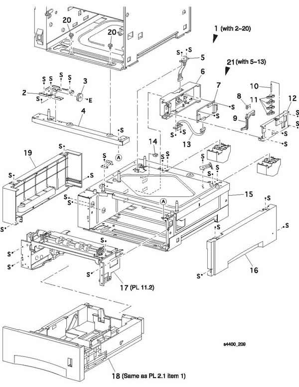
| Item |
Part |
Description |
| 1 |
|
Option Feeder Assembly (with 2-20) |
| 2 |
|
Gear OPT Bracket Assembly |
| 3 |
7E54920 |
Gear OPT I |
| 4 |
|
Top Plate |
| 5 |
162K48431 |
Option Size Harness Assembly |
| 6 |
|
Size Sensor Housing |
| 7 |
160K53061 |
Size Option PWB |
| 8 |
|
CAM Spring |
| 9 |
|
CAM Lever |
| 10 |
|
CAM Shaft |
| 11 |
|
CAM SW |
| 12 |
|
Cover Size Sensor |
| 13 |
162K48420 |
Size Harness Assembly |
| 14 |
|
Clamp |
| 15 |
|
Main Frame Assembly |
| 16 |
802E04931 |
Right Side Cover |
| 17 |
22K56912 |
Feeder Assembly |
| 18 |
109R00448 |
Cassette Assembly (Same as PL 2.1 item 1) |
| 19 |
802E04920 |
Left Side Cover |
| 20 |
600K79670 |
Screw Kit (quantity 3) |
| 21 |
802K09980 |
Size Sensor Housing Assembly (with 5-13) |
| S |
600K79660 |
Hardware Kit (Includes Screws) |
<< Back to Top of Page
PL 11.2 550 Sheet Feeder (2 of 2)

| Item |
Part |
Description |
Item |
Part |
Description |
| 1 |
22K56912 |
Feeder Assembly 2 Kit (with 2-42) |
26 |
|
Roller Assembly (P/O item 43) |
| 2 |
22K55001 |
Turn Roller Assembly (with 3) |
27 |
|
Gear 25T |
| 3 |
121K20151 |
Turn Clutch Assembly |
28 |
|
Gear 31T |
| 4 |
|
Spring Extension |
29 |
809E11610 |
Nudger Spring |
| 5 |
809E11630 |
Chute Spring |
30 |
|
Gear 4 |
| 6 |
120E16960 |
No Paper Actuator |
31 |
|
Gear 2 |
| 7 |
830E18132 |
Actuator Support |
32 |
|
Gear Cover |
| 8 |
|
Feeder Frame Assembly |
33 |
|
Bracket |
| 9 |
|
Clamp |
34 |
|
Gear 3 |
| 10 |
|
Left Latch Spring |
35 |
|
OPT Gear |
| 11 |
|
Low Paper Actuator (P/O item 43) |
36 |
160K52781 |
Feeder PWB |
| 12 |
|
Low Paper Support Actuator (P/O item 43) |
37 |
121K19010 |
Feed Clutch Assembly |
| 13 |
130E81970 |
Low Paper Sensor |
38 |
|
Bearing |
| 14 |
162K47211 |
N/Sensor Harness Assembly |
39 |
|
N/Motor Harness Assembly |
| 15 |
|
Roller 7 Support |
40 |
|
Socket |
| 16 |
|
Turn Chute |
41 |
|
Paper Tray Stopper |
| 17 |
|
Roller 7 |
42 |
|
Clamp |
| 18 |
|
Feeder Cover |
43 |
600K79550 |
Feed Roller Kit (item 26- quantity 3) |
| 19 |
600K79320 |
Feeder Assembly (with 20-28) |
44 |
600K79640 |
Socket & Harness Kit (with 39, 40) |
| 20 |
|
Feed Shaft |
45 |
600K79652 |
Actuator & Support Kit (with 11, 12) |
| 21 |
|
Bearing |
S |
600K79660 |
Hardware Kit (Includes Screw) |
| 22 |
|
Nudger Support Assembly |
|
|
|
| 23 |
130E81970 |
Stack Height Sensor |
|
|
|
| 24 |
|
Gear Clutch |
|
|
|
| 25 |
|
O/W Clutch Assembly |
|
|
|
<< Back to Top of Page
PL 12.1 Envelope Feeder (1 of 2)

| Item |
Part |
Description |
| 1 |
|
Envelope Feeder Assembly (with 2-24) |
| 2 |
54E14453 |
Top Chute |
| 3 |
|
Chute Plate |
| 4 |
|
Sensor Harness Assembly |
| 5 |
130K60390 |
Exit Sensor Assembly |
| 6 |
|
Retard Holder |
| 7 |
|
Retard Spring |
| 8 |
|
Feeder Bearing |
| 9 |
59E93940 |
Exit Pinch Roller |
| 10 |
|
Pinch Roller Shaft |
| 11 |
|
Pinch Cap |
| 12 |
|
Pinch Spring |
| 13 |
|
Torque 29 Clutch Assembly |
| 14 |
600K79310 |
Retard Roller Assembly (with 15) |
| 15 |
|
Retard Roller (P/O item 14) |
| 16 |
31E93291 |
Weight Arm |
| 17 |
|
Weight Cover |
| 18 |
|
Weight Holder |
| 19 |
|
Envelope Left Side Guide |
| 20 |
|
Envelope Right Side Guide |
| 21 |
|
Envelope Feeder Sub Assembly |
| 22 |
|
Pinion Gear |
| 23 |
|
Bottom Cover |
| 24 |
|
Tray Extension |
| S |
600K79660 |
Hardware Kit (Includes Screw) |
<< Back to Top of Page
PL 12.2 Envelope Feeder (2 of 2)

| Item |
Part |
Description |
| 1 |
|
Envelope Feeder Sub Assembly (with 2-31) |
| 2 |
|
Gear Cover |
| 3 |
7E27420 |
Gear 29 |
| 4 |
|
Gear Drive 21 |
| 5 |
7E36080 |
Gear 23 |
| 6 |
121K87180 |
Torque 25 Clutch Assembly |
| 7 |
|
Feeder Bearing |
| 8 |
7E28780 |
Idler 21 Gear |
| 9 |
121K87201 |
One Way 26 Clutch Assembly |
| 10 |
|
Elec Clutch Bearing |
| 11 |
121K87190 |
Feed Clutch |
| 12 |
6E47120 |
Clutch Shaft 17 |
| 13 |
121K87210 |
One Way Clutch Assembly |
| 14 |
|
Transport Roller Assembly (with 16) |
| 15 |
|
Transport Roller |
| 16 |
|
Bottom Roller Assembly |
| 17 |
|
Envelope Pinch Roller |
| 18 |
|
Feed Belt |
| 19 |
|
Main Chassis |
| 20 |
|
No Paper Actuator |
| 21 |
130E81970 |
No Paper Sensor |
| 22 |
|
Feed Roller Assembly 1 (with 23) |
| 23 |
|
Feeder Roller |
| 24 |
|
Feed Roller Assembly 2 (with 23) |
| 25 |
|
Envelope Connector |
| 26 |
|
Main Harness Assembly |
| 27 |
|
Clutch Harness Assembly |
| 28 |
|
Envelope PWB |
| 29 |
|
No Paper Harness Assembly |
| S |
600K79660 |
Hardware Kit (Includes Screw) |
<< Back to Top of Page
PL 13.1 Duplex (1 of 2)

| Item |
Part |
Description |
| 1 |
|
Duplex Assembly (with 2-6) |
| 2 |
|
Turn Chute Assembly |
| 3 |
|
Chute Assembly Connector |
| 4 |
54K15061 |
Upper Chute Assembly |
| 5 |
|
Duplex Drive Cover |
| 6 |
|
Lower Duplex Chute Assembly |
| S |
600K79660 |
Hardware Kit (Includes Screw) |
<< Back to Top of Page
PL 13.2 Duplex (2 of 2)

| Item |
Part |
Description |
| 1 |
|
Lower Duplex Chute Assembly (with 2-18) |
| 2 |
59K12151 |
Duplex Roller Assembly |
| 3 |
3E47580 |
Duplex Bearing |
| 4 |
|
Duplex Gear 17/Pulley |
| 5 |
|
Duplex Bearing |
| 6 |
|
Duplex Gear 18 |
| 7 |
|
Duplex Gear 17/39 |
| 8 |
127K36520 |
Motor Assembly |
| 9 |
423W15455 |
Synchronous Belt |
| 10 |
|
Lower Duplex Chute |
| 11 |
|
Duplex Latch |
| 12 |
|
Duplex Latch Spring |
| 13 |
|
Duplex Sensor Harness |
| 14 |
130E81970 |
Duplex Home Sensor |
| 15 |
160K53051 |
Duplex PWB |
| 16 |
|
Duplex Cover |
| 17 |
130K83310 |
Duplex Sensor |
| 18 |
|
Duplex Handle Label |
| S |
600K79660 |
Hardware Kit (Includes Screw) |
<< Back to Top of Page
PL 14.1 Duplex (1 of 2)

| Item |
Part |
Description |
| 1 |
|
Stacker Assembly (with 2-13) |
| 2 |
50K38632 |
Exit Tray Assembly |
| 3 |
|
Tray Spring |
| 4 |
50E89161 |
Exit Tray |
| 5 |
12E09550 |
Weight Link |
| 6 |
802E02773 |
Rear Cover |
| 7 |
802E02755 |
Stacker Cover |
| 8 |
54K22380 |
Inner Exit Chute Assembly |
| 9 |
|
Hook Cover |
| 10 |
|
Lower Cover |
| 11 |
|
Cover Hinge |
| 12 |
|
Left Cover Spring |
| 13 |
|
Right Cover Spring |
| S |
600K79660 |
Hardware Kit (Includes Screw) |
<< Back to Top of Page
PL 14.2 Duplex (2 of 2)

| Item |
Part |
Description |
Item |
Part |
Description |
| 1 |
54K22380 |
Inner Exit Chute Assembly (with 2-43) |
26 |
|
Stacker Guide |
| 2 |
|
Stacker Harness Assembly (J21-P202) |
27 |
|
Stacker Holder |
| 3 |
|
PWB Holder |
28 |
|
Exit Shaft |
| 4 |
160K88240 |
Stacker PWB |
29 |
|
Mid Roller Assembly |
| 5 |
|
Ground Plate |
30 |
|
Stacker Pinch Roller |
| 6 |
127K28640 |
Drive Motor Assembly |
31 |
|
Mid Pinch Spring |
| 7 |
|
Gear Exit 20 |
32 |
54E14431 |
Inner Exit Chute |
| 8 |
|
Exit Bearing |
33 |
802K05770 |
Offset Assembly (with 34-38) |
| 9 |
|
Gear 27 |
34 |
|
Offset Motor Assembly |
| 10 |
|
Gear 26 |
35 |
|
Offset Housing |
| 11 |
|
Gear 47W |
36 |
130E81970 |
Stacker Home Sensor |
| 12 |
|
Gear Exit |
37 |
|
Offset Lever |
| 13 |
|
Static Eliminator |
38 |
|
Core Gear |
| 14 |
|
Gear Housing |
39 |
|
Ferrite Core |
| 15 |
121K20551 |
Direction Solenoid |
40 |
|
Stacker Wire Assembly |
| 16 |
11E09450 |
Solenoid Lever |
41 |
|
Sensor Bracket |
| 17 |
|
Solenoid Pin |
42 |
|
Saddle Edge |
| 18 |
130K84220 |
Exit Sensor Assembly |
43 |
|
Exit Pinch Spring |
| 19 |
120E17191 |
Stack Full Actuator |
S |
600K79660 |
Hardware Kit (Includes Screw) |
| 20 |
130E81970 |
Stack Full Sensor |
|
|
|
| 21 |
|
Stacker Sensor Harness Assembly (J224-225, J226, J227, J228) |
|
|
|
| 22 |
|
Offset Roller Assembly (with 23-26, 43) |
|
|
|
| 23 |
|
Exit Roller Assembly |
|
|
|
| 24 |
|
Exit Pinch Roller |
|
|
|
| 25 |
|
Offset Bearing |
|
|
|
<< Back to Top of Page
<< Back to Phaser 4400 Support...
|
|